
Introduction of Natural Draft Cooling Tower
Natural Draft Cooling Towers rely on buoyancy-driven airflow to remove heat from circulating water. As there is no mechanical fan driving the air, the performance of the tower is strongly dependent on the pressure field, atmospheric wind conditions, tower geometry and the way air enters the lower portion of the tower.
In this CFD study, the airflow behaviour of a natural draft cooling tower was investigated under representative operating and wind conditions. The primary objective was to understand the airflow distribution around the tower, identify regions of flow disturbance and recirculation, and evaluate how the surrounding airflow influences the natural draft performance of the cooling tower.
How Does a Natural Draft Cooling Tower Work?
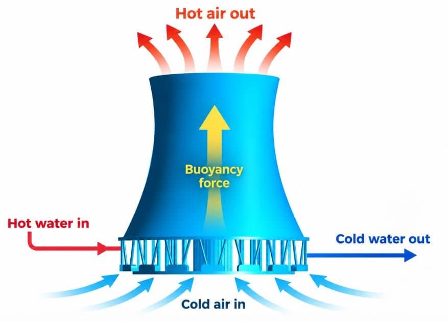
A natural draft cooling tower operates because warm, relatively low-density air inside the tower rises naturally through the tower structure. As this warm air moves upward and exits through the top, cooler ambient air is drawn into the lower portion of the tower. This continuous circulation of air provides the airflow required for heat rejection.
For the cooling tower to operate effectively, the incoming air should be distributed as uniformly as possible. External wind can disturb this natural flow by creating pressure differences around the tower, resulting in asymmetric airflow, localized low-velocity regions and, in some cases, recirculation.
This makes the aerodynamic behaviour of a natural draft cooling tower an important consideration when investigating its performance.
CFD Analysis Approach
A three-dimensional CFD model was developed to investigate the airflow behaviour around and through the natural draft cooling tower. The surrounding atmospheric region was included so that the interaction between the tower and external wind could be captured.
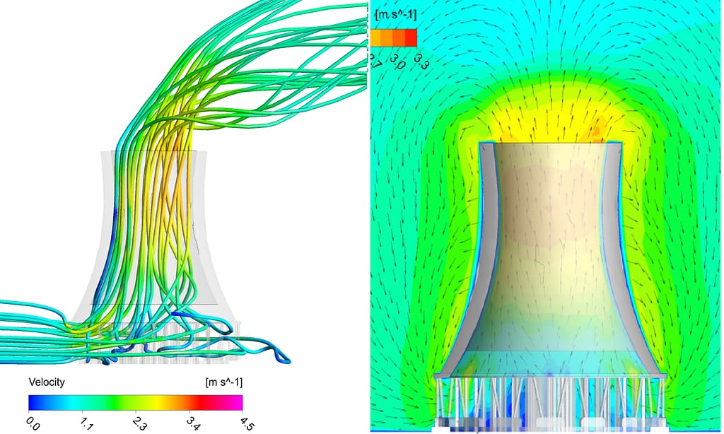
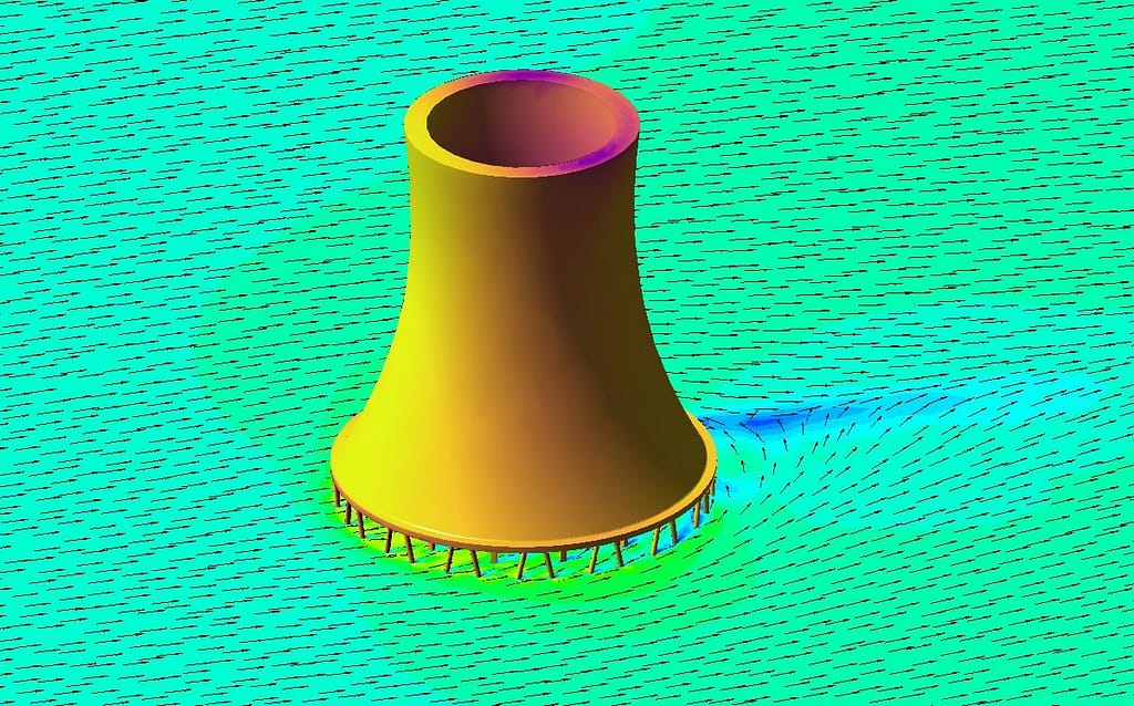
The analysis considered the effects of wind direction and velocity on the flow field around the tower. Velocity contours, velocity vectors and streamlines were used to understand the movement of air into the tower and its subsequent upward movement through the natural draft region. Pressure distribution was also examined to understand how the surrounding wind influences the pressure field and airflow entering the tower.
The CFD approach allowed the flow to be investigated not only at the tower outlet but throughout the complete flow domain. This was particularly useful for identifying areas of airflow blockage, non-uniformity and recirculation that may not be apparent from overall flow-rate calculations.
Results and Observations
The CFD results showed that the external wind significantly influences the airflow pattern around the cooling tower. On the windward side, the incoming atmospheric flow interacts directly with the tower structure, while on the opposite side, a region of disturbed and relatively lower-velocity flow can develop.
The streamlines also showed that the airflow entering the lower region does not always move directly upward into the tower. Under certain wind conditions, a portion of the air can circulate around the bottom region before joining the main upward flow. This creates a non-uniform airflow pattern and indicates that the lower section of the tower is an important region for aerodynamic improvement.
The results demonstrate that evaluating only the average airflow rate is not sufficient to understand natural draft cooling tower behaviour. The distribution of airflow, local recirculation, pressure variation and crosswind effects are equally important when investigating the performance of the tower.
Improving Airflow Using Perforated Openings
One potential approach identified from the aerodynamic investigation is the use of controlled openings or perforations in the lower/windbreak region.
A completely solid windbreak or obstruction can alter the pressure distribution and potentially create larger recirculation zones behind the obstruction. Introducing appropriately designed openings can allow a controlled amount of atmospheric air to pass through the barrier rather than forcing the entire flow around it.
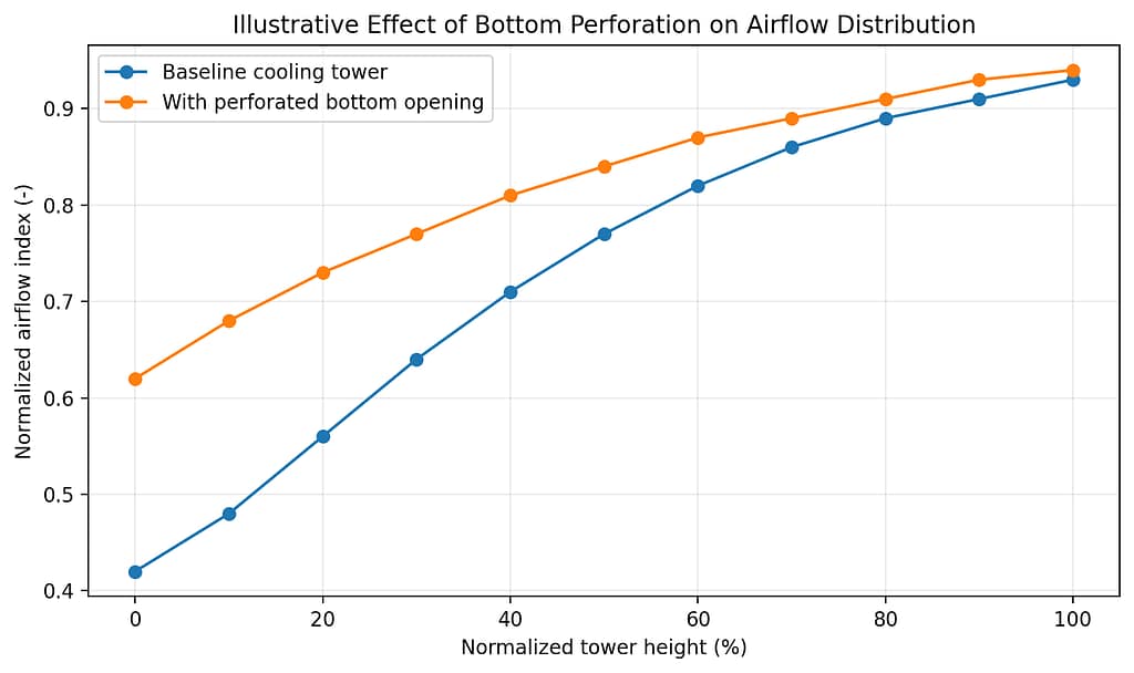
The concept of using perforated windbreak walls or openings with different degrees of permeability can therefore be investigated using CFD. By varying the opening arrangement, height, penetration length and perforation percentage, the airflow distribution around the lower portion of the cooling tower can be optimized. These types of configurations are commonly evaluated to improve airflow uniformity and reduce adverse aerodynamic effects.
For this project, the CFD results indicate that improving the airflow path near the bottom region can help reduce localized recirculation and provide a more favourable airflow distribution into the natural draft tower.
Conclusion
The CFD simulation provided a detailed understanding of the airflow behaviour around the natural draft cooling tower and demonstrated the influence of external wind on the internal and surrounding flow field.
The most important observation was the presence of non-uniform airflow and localized recirculation near the lower region of the tower. This highlights the importance of considering the complete aerodynamic environment rather than evaluating the cooling tower only from its overall airflow or thermal performance.
The study also demonstrates how CFD can be used to evaluate practical design modifications such as windbreak walls, controlled openings and perforated arrangements. By optimizing the opening configuration, it is possible to investigate ways of improving airflow distribution, reducing recirculation and supporting more effective natural-draft operation.
For more information and professional CFD consulting services, visit mail us on info(at)cfdconsultantsindia.com